The brain of the house, in the cabinet
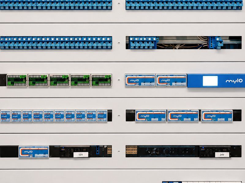
myIO is a central controller that sits in the distribution cabinet, on a DIN rail. The wires of the wall buttons, the sensors and the thermometers run here, and from here the wires go out to the lights, the blind motors and the pumps. myIO watches the inputs and switches the outputs according to your settings.
Every decision is made in myIO: the timers, the automations and the heating control run here, not on a remote server. That is why it works without the internet, and if the connection drops, the house carries on as before. How the wires get to the cabinet is covered on the Who installs it? page.
Inputs: buttons, sensors, thermometers
An input can be anything that closes or opens a contact between two wires: a push button, a door/window, motion or smoke sensor, a dusk switch. So you can pick switches from any manufacturer; the design is up to you. myIO tells a short press from a long press, so one button can do two things: a short press switches the lamp, a long press the whole room.
The thermometers fit in the switch box and measure in steps of 0.06 °C. Humidity sensors and energy meters can be connected too.
Outputs: relays and dimmers
myIO does not switch mains voltage directly: relays in the cabinet switch the lamp, the blind motor, the pump or the boiler, and myIO controls the relays. Any relay will do, there are no special requirements, so the electrician picks the one that suits the load and the regulations, from any manufacturer. LED strips and dimmable lamps are set to a brightness, and a mixing valve is opened step by step.
myIO also protects the outputs: the two directions of a blind never get power at the same time, and when a heating circuit starts, its pump starts by itself.
The software: in the browser
You set up myIO on its own web interface, from any browser. No programming needed: the setup wizard guides you, you press the button on the wall, myIO recognises it, and you choose what it should switch. A house can be set up in a few hours, and you can change it any time later.
Here you find the timers (also tied to sunrise and sunset), the groups, the saved setups that you load with a button or a timer, the users with their own rights, and the log of temperature and consumption.
Why so simple?
The on-board computer of the Apollo spacecraft had only a few kilobytes of memory, yet it took people to the Moon and brought them back. Controlling a house is a far simpler task: watching buttons, switching relays, reading sensors and talking to the user. In principle, a Commodore 64 could do it.
That takes well-written, stable software, not raw power. So myIO is built on mature hardware that stays available for the long term, and it is designed so that both the hardware and the software can be replaced. The more powerful V4 makes room for larger systems and new features, not for complexity.
When you need more: expanders and bridges
When the controller’s inputs and outputs run out, the system grows with expanders. V3 and V4 GIGA take 32-input and 32-output expansion boards; V4 Opta takes the myIO Expander 16, which can also sit further away from the controller. The Expander 16 keeps working with its own settings even if it loses contact with the controller, so the heating, for example, does not stop.
Bridges connect other systems to myIO: KNX devices, DALI and DMX lighting, Modbus energy meters, inverters or heat pumps. beta
Network: app, cloud, integrations
myIO connects to the router by network cable, and on V4 also over WiFi. This is how you reach it from the myIO App and the browser, remotely through myIO Cloud, and how it talks to Home Assistant, Homey and the AI assistant. Over the network it also controls WiFi devices, such as Broadlink devices and Computherm WiFi thermostats. On V4, several myIO controllers can be linked into one system, for example in the house and in an outbuilding. More on the Control page.
Designed to last for decades
- No lock-in: the buttons, the relays and the power supplies are standard parts, and the wiring is star-shaped. If you ever decide against smart control, everything works the same with impulse relays.
- Upgradable: a V3 becomes a V4 GIGA when the electrician replaces the processor board. The wiring, the cabinet and the SD card that holds the settings stay.
- Kept up to date: new features arrive as software updates over the network; no need to go to the cabinet.
- Open: myIO’s communication protocol is open, so anyone can develop a device or an app for it.
For professionals
- Controllers: V3 = Arduino Due (Cortex-M3, 84 MHz, 96 KB RAM, SD card); V4 GIGA = Arduino GIGA R1 (dual-core, 480 + 240 MHz, 1 MB + 8 MB RAM, SD card + internal flash, crypto chip); V4 Opta = Finder Opta (dual-core, 480 + 240 MHz, 1 MB RAM, internal flash, crypto chip).
- Maximum build-out (outputs / inputs): V3 and V4 GIGA 160 / 128, V4 Opta 160 / 160. DS18B20 temperature sensors: 40 (on V4 Opta through the Expander 16); DHT humidity sensors: 8 (V3, V4 GIGA); 0–10 V analogue inputs: 8 (V4 Opta).
- Inputs: NO/NC contacts; events: short press, long press, release. Energy meter: SDM630 (on V4 Opta through the Modbus bridge).
- Outputs: relay (any type), dimming by PWM or 0–10 V. Sensor-controlled output with hysteresis, heating and cooling mode, and mixer mode. Lockout pair (mutual exclusion of two outputs), coupler (one output follows another), group, pump coupling.
- Power supply: V3 and V4 GIGA 5 V + 5–24 V, V4 Opta 12–24 V DC. The controller draws about 5–10 W; a UPS is recommended.
- Mounting: DIN rail, V3 and V4 GIGA 12 modules, V4 Opta 4 modules. Service display: on the controller for V3 and V4 GIGA, on the Expander 16 for V4 Opta.
- Network: Ethernet, plus WiFi on V4. Concurrent connections (sockets): V3 and V4 GIGA 8, V4 Opta 4. Communication over HTTP (web interface, app) and MQTT (Home Assistant Discovery); the protocol is open, and every request needs a username and password.
- Logging: temperature, humidity and consumption to CSV (on the SD card, on V4 Opta to internal flash), event log. Accurate time from a time server (NTP).
- Expanders: Ext32 In / Ext32 Out over I2C (V3, V4 GIGA); myIO Expander 16 on an RS485 bus, with standalone mode (V4 Opta; V4 GIGA: coming soon). Bridges over RS485 (KNX, DALI, DMX, Modbus): beta on V4 Opta, coming soon on V4 GIGA.
- myIO Link (V4): linking several controllers into one system.